Mechanical, Electrical and Plumbing Drawings
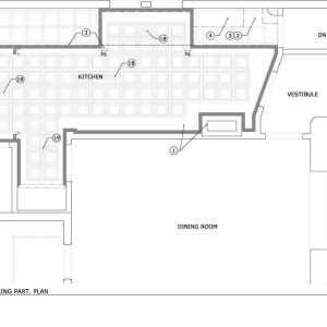
Engineering systems in a construction project are detailed on several floor plans, drawings and technical specification documents.
Mechanical systems are otherwise known as Heating, Ventilation and Air Conditioning (HVAC) equipment, including central air conditioners, mini-split systems, geothermal heat pumps and other equipment.
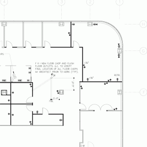
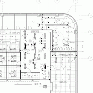
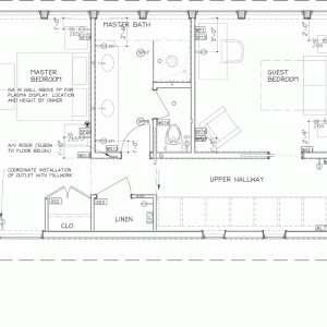
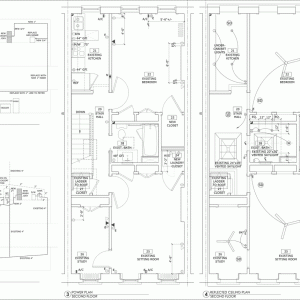
Electrical drawings are often called power and signal plans to include communications and audio equipment, in addition to power for all electrical appliances and receptacles. Reflected ceiling plans show the location of ceiling light fixtures and wall sconces, smoke/CO detectors, exit lights and emergency strobes. Ceiling and floor plans can also show the location of HVAC diffusers, return air registers and ductwork.
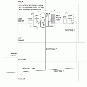
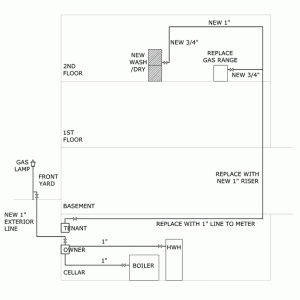
Plumbing drawings show the location of gas and plumbing fixtures in kitchen and bath, swimming pools and water features. Sprinklers for fire suppression are shown on reflected ceiling plans.
Riser diagrams are also used to show the vertical layout of plumbing fixtures and “risers” up from the lower floors for water supply, drainage and ventilation. Electrical riser diagrams are used for complex electrical and communications wiring.
